Application Considerations
- September 20, 2016
- 4.62 Thousand
SpiralTrac can be beneficial in most process equipment, regardless of application. It's time to consider using it.

SpiralTrac™ is designed to improve the operating environment for the mechanical seal or packing through the use of a variable geometry spiral grooving system that achieves several functions:
- It shears off a volume of the rotating fluid flow in the chamber on each revolution, and pumps that volume from the bore, spiraling it radially inward. About 60 to 70% of the flow is spilled at the shaft. This creates the circulation within the seal chamber that cools the seal face, and draws abrasives from the cavity bore.
- Draws the other 30 - 40 % of the flow created by the spiral, out of the seal chamber in the exit groove to remove frictional heat.
- Some versions allow air to escape through a specially designed vent at the 12 o’clock position. This prevents air from surrounding and thermally isolating the seal faces. It also avoids product crystallizing on the seal components.
- Collects and expels abrasives from the seal chamber. This avoids cavity and seal erosion, and prevents accumulation, to ensure heat transfer from the faces.
There are instances where SpiralTrac™ performance can be enhanced through the use of better installation techniques or set up. Conversely, there are a few applications in which it cannot be expected to contribute much in terms of improvements. In service, SpiralTrac™ will automatically work to provide the above benefits to the sealing environment, and each individual factor will result in extended service life. This is why customers are astonished at how high the success ratio is, and why it should be installed in most process equipment, regardless of application.
The following list outlines areas that can affect the performance of SpiralTrac™, and therefore have a direct affect upon the seal. These have been realized through feedback from customers and specialists, or through direct observations over the past 20 years.
1. Make sure the exit groove is clear all the way through to the impeller, with space behind the impeller to allow contaminants to get out.
A SpiralTrac™ was installed into a backplate, and when the impeller was mounted, the boss came hard up against the back of the device, blocking the exit from expelling the dirt. The same situation can be created by a step in the shaft or sleeve. This leads to contaminants accumulating in the chamber, and seal failure.
2. When using a device that rests up against a cast in throat, make sure that the throat will allow the expected size of contaminant to pass underneath.
These types of SpiralTrac™ are pressed through the cavity to rest against the cast in throat at the bottom. The exit from the cavity is the gap between the shaft and the cast in throat at the bottom. Flush is often drawn from ponds, lagoons, streams etc. and large contaminants could be introduced into the chamber that SpiralTrac™ will capture, and deliver to the opening between the shaft and the cast in throat. If the particulate is too large to pass under, it will accumulate at this point, and if contaminants accumulate, the exit groove will eventually plug and the SpiralTrac™ benefits will be lost. If this is identified as a problem, the bottom of the seal chamber should be opened up to allow the abrasives to pass under, or a finer screen should be used in the main supply line.
3. Check for air in the process.
As shown in the SpiralTrac™ video, air in the process will be broken into microscopic sized bubbles, and will make clear water appear gray. Any of this air in the fluid column between the impeller and the backplate, extending out into the volute, is in a centrifuge with its center at the shaft. The air will be driven inward to form a single bubble, growing outward from the shaft. When centripetal force grows strong enough, the air will be driven into the cavity and around the seal. Seal failure can occur rapidly if the seal faces are not protected by a quench or double seal arrangement, or if a small flush is not used. Note that the SpiralTrac™ air vent cannot help with air that enters during operation of the pump, because centripetal force drives the air inward and around the shaft and seal. A quench, double seal, or flush are required to cool the seal faces.
4. Make sure the air vent is oriented toward the top of the seal cavity.
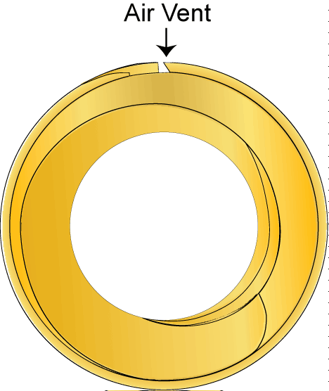 One device was found to be installed with the air vent not at the top. This occurred because the backplate did not fit at any specific orientation. Care must be taken to ensure that the backplate is fitted with the SpiralTrac™ air vent at the top so that air does not trap in the cavity during flooding of the pump.
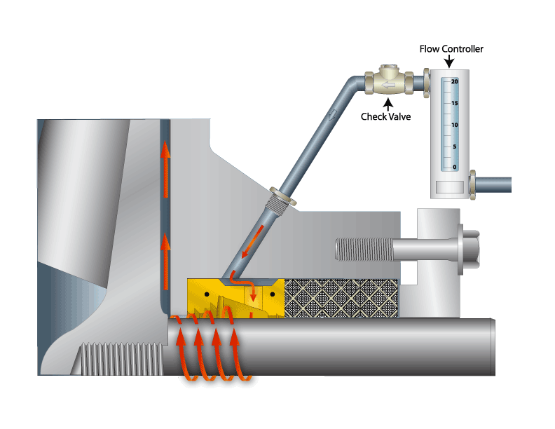
5. Put check valves on any flush connections.
The pressure fluctuates in most flush systems, and when it drops below chamber pressure, a reverse flow will occur that can bring contaminant into the chamber and the flush piping. This can block the supply pipe and prevent the flush from operating permanently. Also with the split type, the reverse pressure can displace the device forward onto the back of the seal, blocking the spiral groove, and preventing it from operating. The simple addition of a check valve prevents all of this from occurring.
6. Ensure that the shaft and housing are concentric.
If it is not, you could have issues installing SpiralTrac™, or run the risk of damaging it during operation.
7. Any slurry flooded into the seal chamber must be fluid enough at start up to rotate freely.
SpiralTrac™ does not centrifuge the abrasives: It counts on the rotation of the shaft and seal to drive the fluid, and achieve separation of the solids to the bore. Some slurries can have 40 to 60% solids, that settle out when flooded into the cavity. Sometimes they can settle to form a solid mass at the bottom of the chamber that will not break up when the pump starts. We have found that this problem can often be avoided if a small flush is injected during flooding, and again for a few minutes after starting.
10. Install SpiralTrac™ Version P with 3 rings of packing above.
 The most consistent results have been obtained when SpiralTrac™ Version P has been installed with minimum 3 rings of packing before the gland when the cavity pressure is even moderate to high. The use of 2 rings on small shafts, and when the chamber pressure is minimal has not been a problem, but otherwise 2 rings is just not enough to achieve the desired drip rate leakage.
When only 2 rings of space are available, a custom device may be designed around the chamber dimensions, or a new flush injection hole can be drilled, or some customers have made box extensions onto the front of the cavity to make additional room.
Normal packing gland adjustments will still be necessary as the packing set conforms to the cavity and sleeve under pressure.
11. Watch first obstruction dimension.
When ordering split SpiralTrac™ for field installation, remember that they have to be assembled onto the shaft before insertion into the chamber. This means that they must be shorter than the distance to first obstruction. Sometimes this means that the SpiralTrac™ must be manufactured in two individually split sections, if the device is longer than the available space.
12. Watch for the “obvious”.
The spiral in the seal version must face the mechanical seal, and the direction of rotation must progress from the bore to the shaft in the direction of shaft rotation. Don’t install it backwards…the SpiralTrac™ is very capable of demonstrating in a hurry that it can pump contaminants from one side to the other, especially if it is installed to pump into the cavity. Also note that double-ended pumps require one device of each direction of rotation. When installing SpiralTrac™ Version P, make sure to align the lantern ring groove with the flush injection port: if not, it is probably about to be installed backwards.
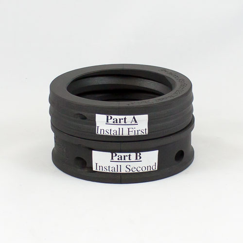
There are mulitple ways you can be sure to install SpiralTrac™ correctly:
- Look for the sticker on the device.
- The part number is always engraved on the impeller side.
- Version P SpiralTrac extraction holes are always facing the drive end.
Factors Beyond the control of SpiralTrac
SpiralTrac™ is a sophisticated bushing with a spiral groove cut into the seal side. The spiral is cut under computer control, and its geometry varies in such a manner that it acts as a pumping ring, using the rotational flow of the fluid. The operation of the SpiralTrac™ counts on centrifugal effects of the rotational flow to throw contaminants to the bore, so that it can draw them away. In the process of accomplishing this, the fluid is circulated around the seal and exchanged into and out of the cavity, removing frictional heat. A vent at the top permits air to escape from the cavity during flooding, again reducing heat generation.
Please note that this description does not include any capability that will enable mechanical seals to handle situations such as:
- Bearing failures
- Broken shafts
- Cavitation (or running pumps with discharge or suction closed)
- Dry running of the pump
- Atmosperic side crystallization
- Products that adhere directly to surfaces (e.g. latex)
These are all problems that will directly cause damage to the mechanical seal (and most will probably lead to damage to the SpiralTrac™ as well). They are situations or operational conditions that have to be dealt with in some other manner.
The research information provided as background for the SpiralTrac™ only outlines the dynamics occurring in the seal chamber of the pump during normal operation. When the pump is operating well outside its operating design point, the forces on the shaft will cause the bending and flexing that will rapidly cause seal failure. The addition of SpiralTrac™ to this situation will make the seal environment better, but with the seal being thrashed about at pumping speed, an expectation of improved life is not realistic.
Don’t expect SpiralTrac™ to make drinking water in the seal chamber. Its job is to continuously remove contaminants as they are centrifuged to the bore, and in this way prevent particulate from accumulating and impeding heat transfer from the seal faces. It should ensure an active and free flow of fluid around the seal.